Designed and built to the rigid electrical and mechanical specifications
of
the U.S. Federal Aviation Administration and certified for use under
extreme environmental conditions, Servo DF systems for both UHF and
VHF, are currently in use in hundreds of locations throughout the world.
These systems, over the past 30 years, have with stood searing
temperatures in deserts of Egypt, hurricanes in the Caribbean and
freezing snow, wind and ice conditions in Alaska and Canada.
Developed in the 1940's by Servo Corporation, the Quasi-Doppler DF
concept simulates the effect of a revolving single dipole antenna around
the circumference of a circle. In this case the vertically polarized dipoles
are electrically commutated to phase modulate the individually
received signals on a sampled data basis. This phase modulation
produces a DF sine wave of approximately 250 Hz which has a
phase relationship proportional to the angle of arrival of the DF
signal. The results are displayed instantaneously in the digital
bearing readout and ring-of-light display on both the
Receiver/Bearing Processor and the Bearing Display/Control
Assembly.
Detailed Equipment Description
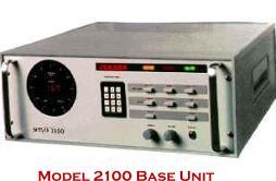
The Receiver/Bearing Processor is installed at the antenna site
and connected via cables to the DF antenna. It is a rack-mounted
unit which contains all the necessary electronic equipment to
receive and process RF signals. For UHF/VHF operation, two of
these devices are required. Although the units look identical they
are specifically tuned for their unique operation.
Received RF signals are converted to a digital output suitable to
drive the Bearing and Ring-of-Lights displays on the front panel of
the unit, and for transmission via a system specified modem over
voice-grade telephone lines to a remote control site equipped with
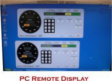
a Bearing Display/Control Assembly. Controls and displays located
on he Bearing Display/Control Assembly are identical to those on the receiver processor. However,
system control is limited to one site only (either local or remote) as determined by the setting of the
LOCAL push-button switch on the Receiver Processor Assembly. Bearing, frequency and other status
information is displayed at both sites regardless of which has control.
Bearing/Display/Control
The Bearing Display/Control Unit is installed at the operations site (e.g. Control tower) and connected
via a 4 wire voice grade telephone line circuit to the Receiver/Bearing Processor unit located at the
antenna site. It is a rack-mounted unit which is similar in physical appearance to the Receiver/Bearing
Processor Assembly. The unit contains all circuits necessary to remotely control tuning of the receiver
(located in the Receiver/Bearing Processor Assembly) and to receive and display the receiver channel
frequency as well as status and bearing data through the use of the modem and associated 4-wire
telephone circuit. The Bearing Display/ Control Assembly will display either VHF or UHF signals
depending upon the position of the optional VHF/UHF switch setting on the unit. Except for the
VHF/UHF optional switch and the REMOTE/Local selector switch, all other front panel functions are
the same as those of the Receiver/Bearing Processor Assembly.
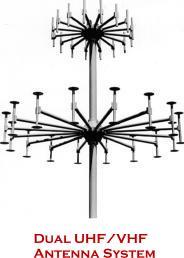
Antenna Assembly (About DF Antennas)
The Series 2100 antenna system comes in various options: 16 element VHF, 8 element VHF, 16 element
UHF and combination 32 element UHF/VHF assembly.
DF2100 Spares (www.df2100.com)


Servo Corporation of America - All rights reserved